|
1909 ‑ No. 2,297, Improvements in Hub Caps for
Detachable Wheels. (The Riley Cycle
Company, Limited and Victor Riley) (Illustrations 4, 5)
This patent only describes the means of securing
the inner and outer hubs together. The patent does not describe how the drive
loads are transferred.
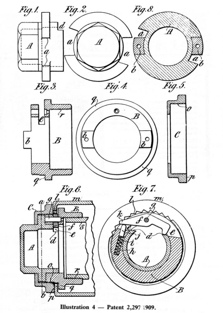
The outer hub is secured to the inner hub by nut
B, which screws onto the inner hub. To turn the nut, the spanner is fitted to
the hexagon machined on outer cap A. The outer cap is loosely held to the nut,
and to the outer hub, by a retaining ring C. Cut‑outs "a" in the cap
engage with lugs "b" on the nut. The lugs are smaller than the cut‑outs,
providing a degree of lost motion between nut and cap which is made use of by
the locking mechanism. A slot "e‑e"
is cut in the cap A, and within this slot is a spring loaded pawl "f"
which is pivoted in the nut B. The pawl engages with ratchet teeth
"l" cut on the inside of the outer hub. When the cap is turned anti‑clockwise
by the spanner, the pawl is lifted when it strikes the end of the slot, and the
ratchet is thus released. The lost motion is now fully taken up, and further
rotation will undo the nut. Flange "q" on the nut pulls the outer hub
off with the nut as it is undone.
The ratchet teeth, although of similar form to
those in the "early" wheel, are cut in the outer hub.
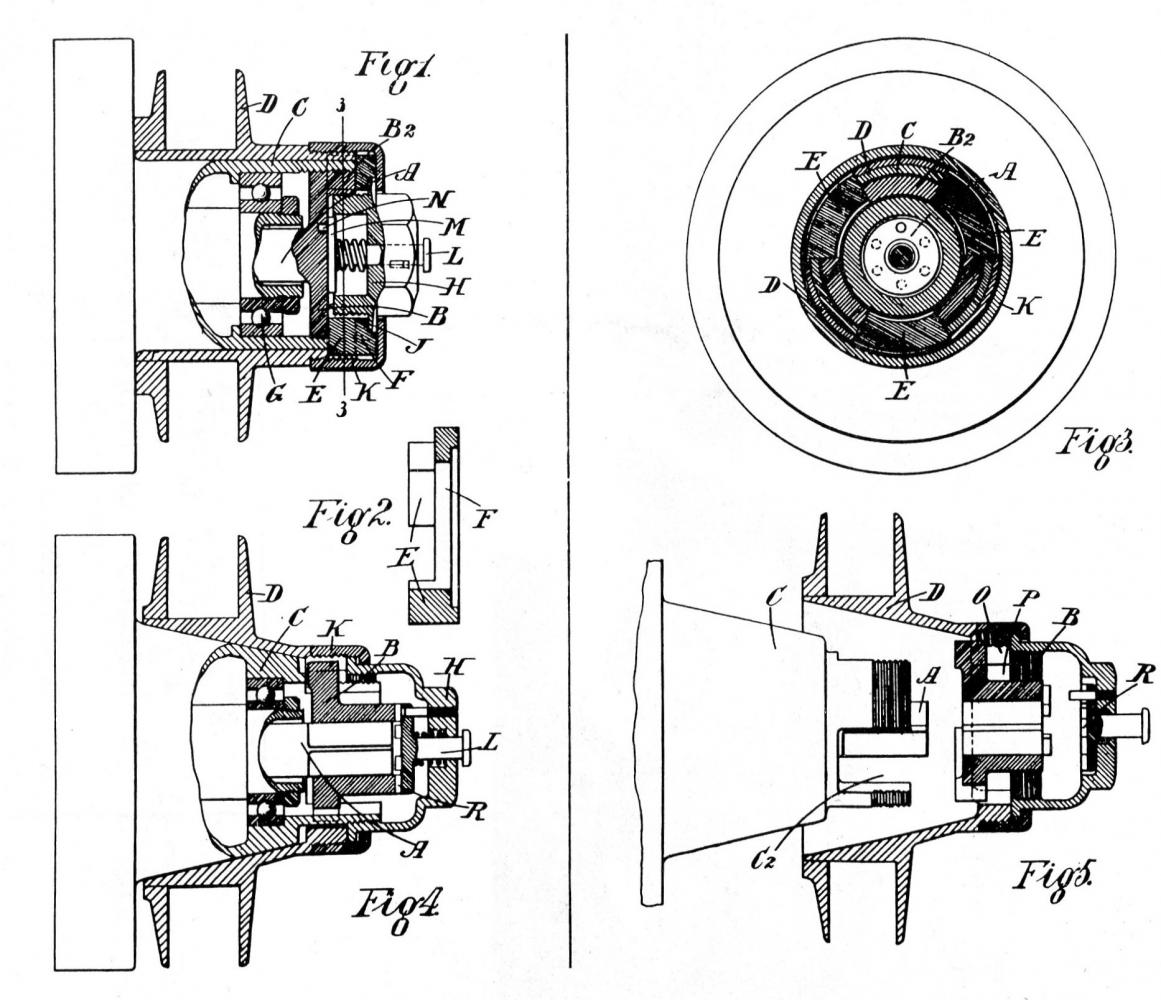
In the 1911 10 and 12/18 h.p. catalogue a
similar nut is shown in section. The main difference is that the thread on the
inner hub, onto which nut B is screwed, is now female.
The catalogue drawing also shows that the drive
is taken by means of projecting studs mounted on the inner hub. The hub is not
tapered. The half shaft is fitted to the inner hub by a taper and key. The
brake drum is fixed to the inner hub.
Riley advertising in 1910 also shows this form of
wheel, complete with a two handled spanner. The spanner shows a feature
mentioned in the catalogue, which prevents it from being removed unless the cap
is in the locked position. When the cap is rotated anti‑clockwise from this
position a projection on the rear of the spanner is trapped behind a flange on
the ring C. When the cap is turned clockwise to tighten the nut the lost motion
between them is first taken up before the nut begins to move. This allows the
ratchet to engage and also brings the spanner projection in line with a cut‑out
in the flange, thus allowing its removal.
"The Car Illustrated" of July 27 1910
devotes a whole page to this type of wheel.
There is every sign therefore that this wheel
was produced. Unfortunately however, I have not seen it fitted to any existing
Riley, but perhaps one still exists on another Edwardian car.
Illustration 5 ‑ 1910
Advertisement for 2,297/1909
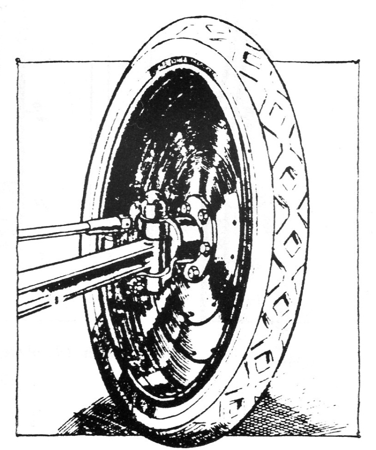
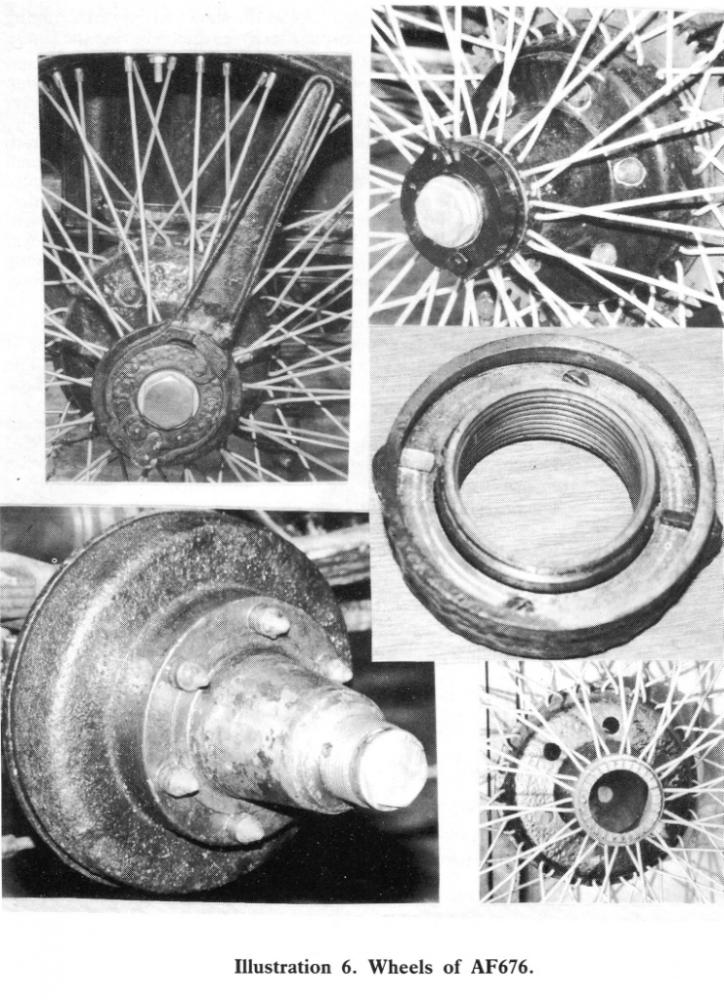
1910 ‑ No. 19,797, Improvements in Detachable
Wheels for Vehicles, and in Spanners for Securing and Removing the same.
(Victor Riley) (Illustrations 6‑8)
This patent describes the wheels fitted to my
own car. I have also seen a set of these wheels fitted to a Deasey JDS. A rally
report in the April 1985 New Zealand Riley Bulletin shows pictures of a 1908 Vauxhall
which had apparently been so fitted in 1912.
The nut 'c' is of built‑up construction, and
screws on to a coarse (8 t.p.i.) thread on the inner hub 'a'. All earlier Riley
designs that I have seen seem to have had a fine thread. Drive is transmitted,
as in the previous design, by pegs on the inner hub, which is again fixed to
the half shafts by a taper and key.
This design introduces to Riley another design
of locking device. A ring of ratchet teeth 'b3' are cut on the outside
end face of the outer hub 'b'. A pair of sprung‑loaded pawls 'd' act on these
teeth. The other ends of the pawls extend beyond the outer face of the nut, and
are provided with flat head‑caps 'd1'. A special ring spanner 'g' is
provided which fits over a pair of lugs 'c4' formed on the outside
of the nut. The recesses into which the lugs fit are longer than the lugs,
allowing lost motion between the spanner and nut.
To remove the wheel the spanner is turned anti‑clockwise.
Claws 'g1' fitted to the spanner slide under the pawl‑caps, lifting
them sufficiently to disengage from the ratchet teeth. Further rotation of the
spanner then turns the nut as the lost motion is taken up. The nut is loosely
held to the outer hub by a left‑ hand threaded retaining ring 'c2',
which in turn also acts as a withdrawal collar pulling the outer hub off as the
nut is unscrewed.
When the spanner is turned clockwise the claws
slide out from under the pawl heads, thus allowing them to operate again. With
further rotation the lost motion is taken up and the nut is tightened, to the
accompaniment of a clicking sound from the ratchets. As a further safety
feature, one of the pawl caps is provided with a hand‑operated swinging cover
'j'. When this cover is closed it covers the head of the pawl and prevents it
from rising. In addition, when the cover is opened, it obstructs the removal
and fitting of the spanner. This means that it is impossible to remove the
spanner unless the cover is closed, which is in itself impossible unless the
pawl is engaged in the bottom of a ratchet tooth.
This type of wheel is shown and described in the
1912 and 1913 10 h.p. and 12/18 h.p. catalogues. It is also shown, in a variety
of sizes, in the 1912 detachable wheel catalogue, which lists 131 different
makes of car to which Riley Detachable Wheels had been fitted. (This claim, by
the way, was kept up to date in the press, and by late 1912 the total had risen
to 180.) They were on display at the April and November 1911 and the March 1912
shows, but I do not know if the April show was their debut. The hub is tapered,
and at the shows Riley were claiming that this feature took 90% of the drive,
thus relieving the studs.
My experience with this design is that it
provides a very quick and reliable means of changing wheels. No hammer is
required although sometimes it is necessary to kick the spanner. The retaining
ring always forces the wheel off. The swinging cover is a failure, since its
pivot 'j1' rapidly wears and then does not prevent the pawl from
disengaging. The cover is meant to be held closed by a small indentation which
engages with a rounded projection 'b3' in the centre of the pawl
cap. In practice centrifugal (or centripetal for academics) force and vibration
mean that the cover flies open as the car is driven. The pawls are still held
in by their springs, and hopefully the wheel was tightened recently, so this is
no real worry. Refurbishing the pivots only provided a temporary cure and soon
they became as loose as before. Perhaps I should fit elastic bands or copper
wire like they have on the wheel centres of Bugatti’s.
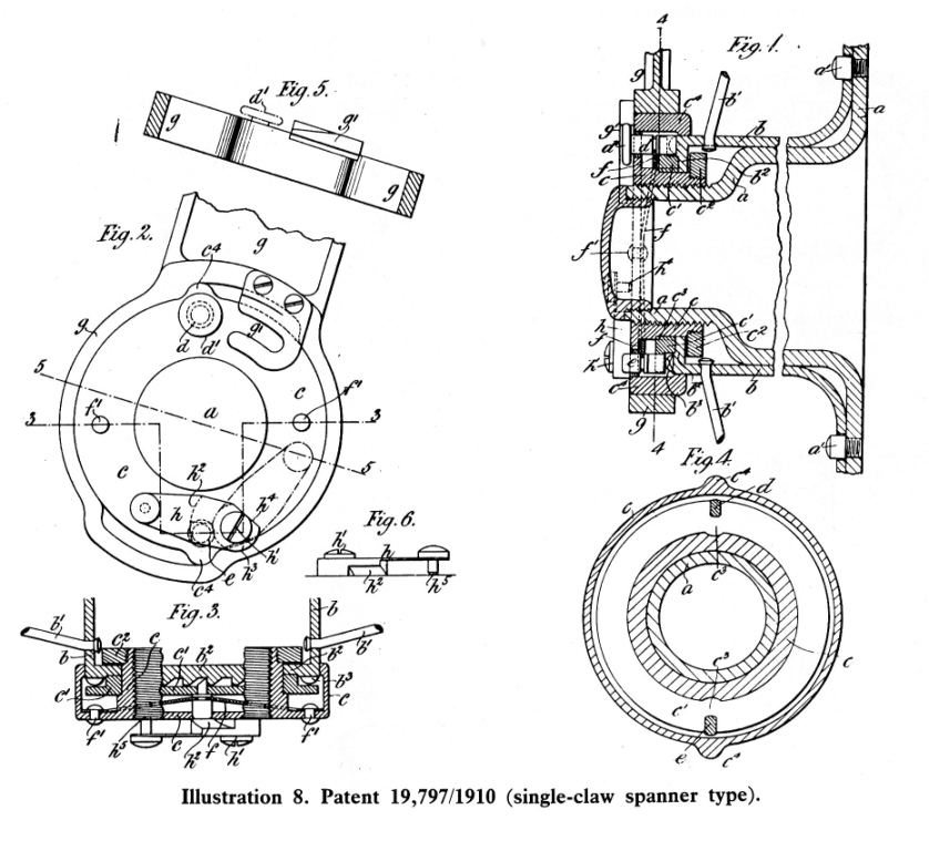
The patent also describes a variation in which
the spring on one of the pawls is reversed and acts so as to disengage it from
the ratchet. The swinging cover 'h' in this case is used to engage this pawl in
one of the ratchet teeth against the action of the spring. Only one claw is now
fitted to the spanner, which once again cannot be fitted or removed unless the
cover is in the closed, safe, state. At
Beaulieu last year (1986) I purchased such a single‑claw spanner, which
indicates this variation was also produced.
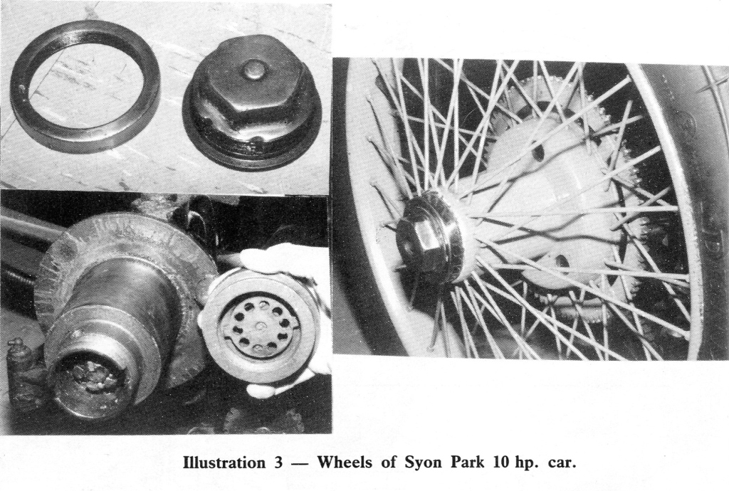
The hexagonal brass hub nut which is visible in
the centre of the nut on my car is decorative (especially if polished), and
retains the bearing grease. It is screwed into the inner hub.
Type Year Chassis Registration Owner
12/18 1911 2254 AF676 Alan Teeder
Deasey JDS 1910 EB485 N. Bradshaw
1908‑Vauxhall 1912 (New
Zealand)
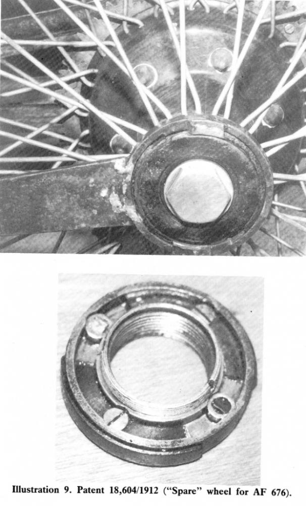
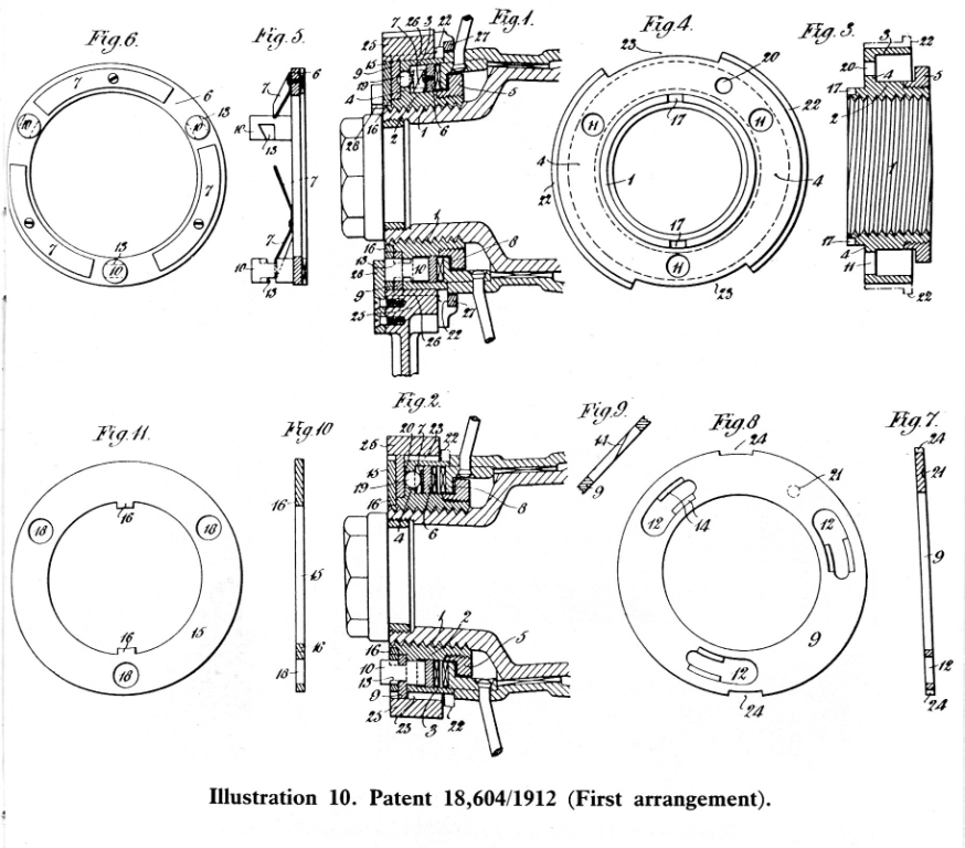
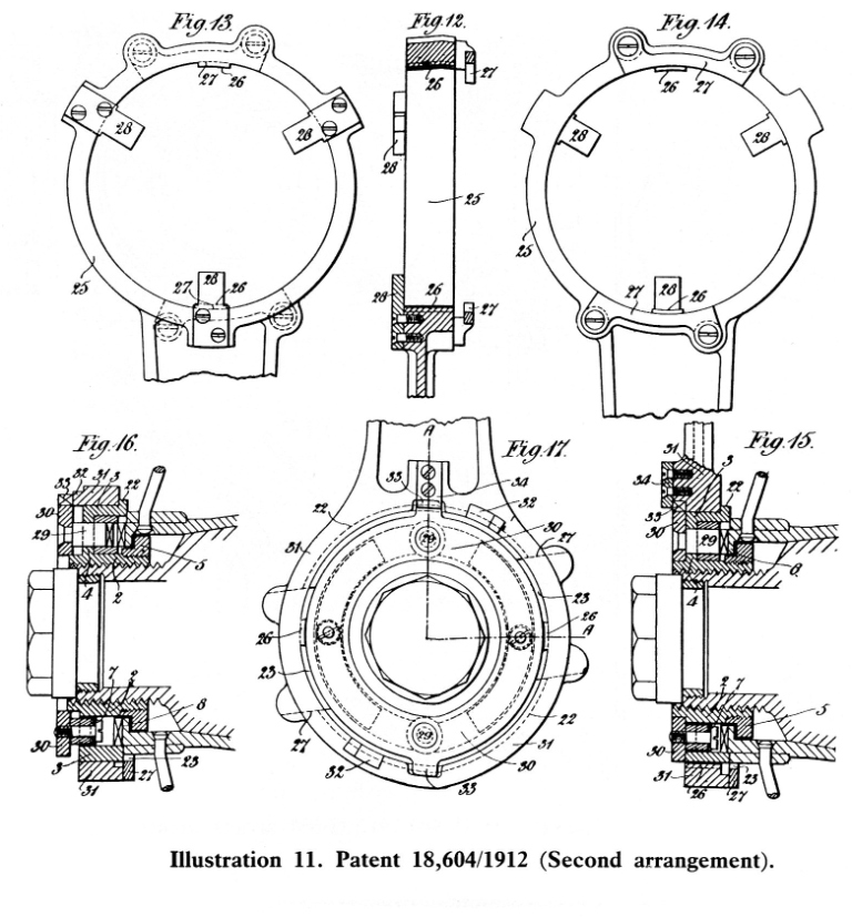
1912 ‑ No. 18,604, Improvements in Detachable
Wheels and in Spanners for Fixing and
Unfixing the same. (Victor Riley and
Stanley Riley) (Illustrations 9‑11)
This specification is derived from the previous
one. It only describes the nut and locking system.
Projections 26 on the inside of the ring spanner
fit in grooves 23 in the outside of the nut to turn it. Two variations are shown for disengaging the
pawls.
In the first arrangement the heads of the pawls
10 pass through slots 12 in a "claw plate" 9. These slots have
inclines 14 machined in them. When the claw plate is rotated anticlockwise
relative to the rest of the nut 1, the heads of the pawls are lifted by the
inclines. Cut‑outs 24 on the outer edge of the claw plate engage with the
projections 26 on the inside of the spanner. The cut‑outs 23 in the outside of
the nut are longer than those in the claw plate so that the latter rotates and
fully lifts the pawls before the spanner tries to undo the nut. A projection 27
at the back of the spanner catches behind the nut and prevents it from being
removed from the nut when the claw plate is rotated into the lift position, in
a similar manner to that described in the 1910 adverts (see 2,297/1909 patent
above). A spring loaded ball 19 is forced into a detent 20 to retain the claw
plate in the safe position.
For the second arrangement the heads of the
pawls are brazed to a ring 30, which forms the outer cover of the nut assembly.
Lifting ramps 32 on the spanner catch under lugs 33 lifting the whole ring when
it is rotated anticlockwise. Otherwise all details are the same.
With both arrangements of this patent the safety
covers in the previous 19,797/1910 design are dispensed with, complete reliance
being placed on the springs.
Last year I acquired a pair of wheels to this
second arrangement. In the patent drawings three sets of pawls are shown, but
mine were only fitted with two.
This type of nut was new at the autumn 1912
motor show, together with the splined hub of patent No. 21,942/1912.
1912 ‑ No. 21,942, Improvements in or relating
to Detachable Wheels. (Victor Riley and
Stanley Riley) (Illustration 12)
This is a very short patent showing two main
things.
The first is the abolition of the driving pegs
which were used on all other known Riley Detachable wheels, except for the 1908
patent. They are replaced by splines. These are rather coarser than those on my
Adelphi. The hub is tapered, which is meant to take the drive. The spline
arrangement was available as an option, from autumn 1912.
The second part of the claim is a method of
manufacturing the outer hub. The splines are formed by locally rolling the hub
down to a smaller diameter, and then broaching. The ratchet ring is formed from
a separate piece of metal from the rest of the hub, and is held in place by the
outer set of spokes, which pass through it and the hub.
The two "spare" hubs that I have are
made to this pattern. To use them on my car I have drilled a set of 6 holes for
the driving pegs. The other dimensions are compatible and for a while I used
one of the nuts with my spare wheel, which was nut‑less when found. This
required the use of spacing rings to allow the pawls to operate. This was not
completely successful as the addition of the spacers meant that insufficient
threads engaged on the withdrawal ring 5. This made this wheel hard to remove,
just like those on my Adelphi are sometimes when the splines bind. To machine
the correct (19,797/1910) nut took a week of evenings, starting with a steel
blank 5" diameter and 2 " long for the main part. Most of this was
removed as swarf.
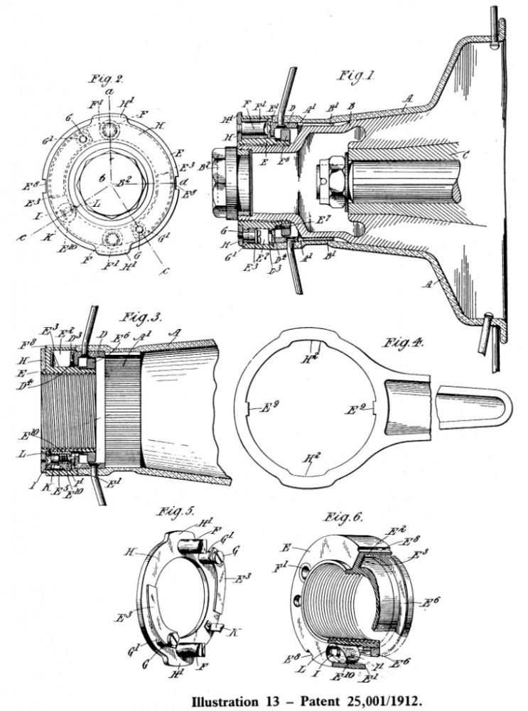
1912 ‑ No. 25,001, Improvements in or relating to Securing‑mechanism for Detachable
Wheels. (Stanley Riley and Rapide
Detachable Wheel Syndicate Limited) (Illustration
13)
This patent, on the face of it, looks like a
development of the previous pair. If you read it however, it says "Patent
of Addition to No. 12,264, 1910". This patent was not one of Riley's, but
was granted to one Stephen Jamieson Ralph, an analytical chemist of
Peterborough. The differences between the two designs are minimal. Mr. Ralph's patent is in turn an improvement
on his own patent, No. 26,380/1909.
The pawls F are brazed to the outer cover H of
the nut. However to release the pawls the cover is pulled outwards by hand.
Inside the body E of the nut is a spring loaded latch K which holds the cover
in this position until the latch is released. The clever bit is that the latch
is released automatically when the nut is unscrewed.
A smooth ring D4 is machined in the
middle of the ratchet teeth D. A plunger
I is pressed into this by a light spring I1. As the nut is unscrewed,
it lifts away from the outer hub A (but not too far because of the withdrawal
ring E6 which holds the nut to the outer hub). The plunger thus
extends further. When the nut is clear of the ratchet ring, the plunger
releases the latch. The pawls are now released and will do their job when the
wheel is next tightened.
A ring spanner with projections E9
engaging in grooves E8 on the nut is used, as in the previous
specifications.
This description relates equally to both the
Riley (25,001/1912) and Ralph (12,264/1910) patents. In view of the
similarities of the rest of the specification to Riley patents 19,797/1910 and
18,604/1912 and Ralph's patent 26,380/1909 I think that there is a small
mystery to clear up.
I have never seen any wheels or other references
to this specification.
1912 Motor Show
Riley introduced hubs to patents No. 18,604/1912
and No. 21,942/1912. A wheel, hub and spanner to this pattern is shown on page
33 or 44 of Birmingham depending on which edition you have. Also made available
as an option for Riley wheels were "Q.D." detachable rims by the
Goodyear Tyre Co. of America. Various makes of detachable rims were very
popular at that time, since they made the removal of tyres much simpler. A
fixed wire wheel for light cars was also shown.
1913 Motor Show (Illustration 14)
New detachable wire wheels for light cars and a
special one for Ford cars were on show. Both were of the now familiar
"bolt‑on" type. These were either 3, 4 or 6 stud as appropriate. The
6 stud wheels used 3 plain drive studs and 3 threaded studs to secure the
wheel.
The wheels were exhibited at overseas motor
shows. There are reports of the Brussels and Russian shows.
Riley detachable wheel for Ford cars
A special type of Riley wheel has been
introduced by Riley (Coventry), Limited, to form a cheap detachable and
interchangeable wire wheel for Ford cars which can be fitted in about an hour
by any Ford dealer. The device was bought
specially
to our notice by Messrs. Albert E. Oakley and Co., of 38, Broad Street, W., who
holds the agency for the southern counties, and from the accompanying
illustration of a back hub wheel it will be seen by those familiar with Ford
practice to consist of a very simple transformation. “A” is the existing wood wheel flange and brake
drum left in situ on the axle even to
the hub cap. The remainder of the
standard wheel is entirely removed. In
the six holes left by the bolts in the flange “A” are bolted permanently three
coned pins and three bolts arranged alternately and shown in detail in the
drawing. The collars on these pins take
the drive. And the nuts on the three screwed bolts hold the new wire wheel to
the existing flange, the hub of the detachable wheel passing over the permanent
hub without disturbing it in any way whatsoever. A brace with a box spanner end passed between
the wire spokes easily reaches and screws up or unscrews the nuts “B”.
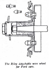 Illustration 14 – Drawing and
legend of the Riley detachable wheel for Ford's.
Non‑Detachable Wheels
To complete my list of early cars, the following
are not fitted with detachable wheels. To remove these wheels it is necessary
to dismantle the cup and cone type bearings.
Type Year Chassis Registration Owner
9 h.p. 1907 1058 508WAR (AR3) J.N.McLaren
9 h.p ? ? ? R.Forsey
9 h.p 1907 1112 YU4031 B.L. Heritage
I think it unlikely that any tricars were fitted
with detachable wheels. Tricar
production effectively ceased at about the same time as the detachable wheels
were introduced. Detachable wheels would not be suitable for the rear wheel in
any case.
Competition
From the beginning the Riley Company was keen to
be seen in competition. Victor Riley in particular was a frequent competitor in
hill climbs. All the car catalogues list the success that Riley’s met with.
In 1908 the French were busy adapting the rules
of Grand Prix racing, and had banned detachable wheels (but not detachable
rims), resulting in Napier withdrawing from that year's event. Victor Riley
wrote to The Autocar “... speed contests such as the Grand Prix should be
intended to 'improve the breed' of automobiles generally, and it would appear
therefore, that detachable wheels should be welcomed, their advantage to the
tourist being obvious."
For the 1911 light car Grand Prix race at
Boulogne two of the entrants were on Riley detachable wheels. The highest
placed of these was a Gregoire which came 5th. A similarly fitted Gregoire came
first in the 1913 Coupe de la Sarthe. Riley made sure that references to these
results appeared in the press.
Readers of "Birmingham" will know that
the Blitzen Benz was fitted with special Riley wheels.
Other Manufacturers (Illustrations 15, 16)
The market leader was the Rudge Whitworth
Company. They were much more aggressive than Riley, who relied upon weekly
adverts in the press and customer goodwill. Other makes included Dunlop,
Sankey, Newton and Bennett, Goodyear, Harris, together with car makers such as
Austin, Talbot, Rover, Vulcan, Humber, Sunbeam, Mass, Hampton making their own
from time to time.
Early Rudge Whitworth wheels transmitted drive
by large slots cut into the inner and outer hubs. A ratchet pawl was released
by the spanner when it was required to remove the wheel. Later on a splined
drive was introduced, and a dead lock pin inserted into the ratchet as a safety
device (Illustration 15).
The ratchet was superseded in 1913 by the Rudge
Whitworth coned locking device that most Riley owners are familiar with (See
Illustration 16). The parallel splines are a loose fit on the inner hub and a
proportion of the car's weight is carried by the nut itself. The nut tightens
on the male coned surface of the end of the outer hub, and has a mating female
cone machined in it. If the nut is loose there will be a gap between these two
cones, allowing the wheel to wobble slightly. The car weight will now be
carried at a single line of contact between the coned surfaces of nut and
wheel. As there is a gap between the cones, the effective diameter of the cone
on the hub is smaller than that of the nut.
The line of contact therefore rolls relative to
hub and nut as the car moves. This, the theory says, can be likened to an
epicyclic gear. Riley owners are well known for their understanding of this
work of the devil and will immediately deduce that in this arrangement, with
the planet gear (i.e. the outer hub) rotating, and the planet carrier fixed
(i.e. in this case always vertical), the outer gear (i.e. the nut) will tend to
rotate backwards. By placing left hand threads on one side of the car, and
right hand threads on the other, this tendency is used to tighten up the nut.
The weight is also carried by the threads at the bottom of the nut, and the
relative motion between the nut and the inner hub induced at this point is in
the same direction, and also adds to the tightening action. Once the nut has tightened, the clearance
between the cones is taken up and the rolling action stops.
So confident were Rudge Whitworth of this theory
that one of their patents describes a nut in which ball bearings are added to
enable it to tighten itself more easily. It was only necessary to fit the nut
hand tight, and after 1/2 mile or so (forward please!) it would require a
spanner to release it. I don't believe theories like this so I always knock my
Adelphi's wheel nuts up tight, especially on the wheels with dodgy splines.
The early Rudge tapered‑cone wheel nuts were
circular, and were removed with a special spanner. The knock‑on ears did not
appear until much later.
The other makes of detachable wheel displayed
every possible type of ratchet or locking pin that could be imagined.
Identification is difficult, since if a name was embossed on a wheel centre
then it was usually that of the car manufacturer. Rudge are an exception to
this and many of their wheel nuts are marked. I have only seen the Riley name
embossed on the "early" type nut fixed to their own 12/18 h.p. cars.
The nuts on my own car carry no identification, even internally.
Riley wheels were also produced under license in
Paris.
Litigation
The reasons for this were that the designs could
be patented or registered. This meant
that you had to pay royalties to use the other firm's design. One or two cases
went to court, and were reported in the automobile press of the time. Napier
claimed from time to time that they held a master patent on all detachable
wheels. They usually lost with that one.
I have found reports of two cases in the
motoring press between J. Pugh of the Rudge Whitworth Company and Riley. In
January 1912 Pugh lost when he claimed that Riley had infringed his registered
design on triple spoking of wire wheels. Riley had however arranged their third
row to cone in the opposite direction to Pugh, and this was good enough to get
away with it.
The second case was incomprehensible to all save
lawyers. Once again J.Pugh challenged Riley, who joined with the British
Gregoire Agency and the Goodyear Motor Wheel Company of Dudley. Pugh won the
first round, which lasted 3 days in 1911. Riley were ordered to destroy the
offending articles and pay Pugh's costs. I think that this includes
compensation for loss of earnings. Riley claimed that the patent was not valid,
and that Pugh, Arrol Johnston and Napier had anticipated its claims.
In 1912 this case reached the appeal court. All
three judges said the patent was valid, but disagreed on engineering details.
The Master of the Rolls said that the Riley design did not indicate when the
hub was fully home, that their grease cap was not part of the hub, and the
inner hub did not pass fully through the outer hub and locking ring. In his
opinion it did not infringe the patent. The other two judges disagreed and gave
a point’s win to Pugh.
The last round, in 1914 again lasted 3 days. The
Lord Chancellor said that Pugh's design was made from a combination of well-known
engineering components, and that he had patented a particular combination of
them. Riley had used a different blend of the same, and other, bits, and this
was sufficiently different to not infringe the patent. Final judgement was
given in favour of Riley, with costs.
By this time Rudge Whitworth had stopped making
wheels with ratchet locks, but this did not stop Pugh from writing to all the
motoring magazines reminding manufacturers that his patents were still valid,
and that he would continue to sue anyone who infringed them.
The "Riley Romance" and
"Birmingham" both say that one action was still outstanding at the
start of the Great War, but give no further details.
Conclusions
In 1912 the Riley Cycle Company decided to stop
car production, and concentrate on wheels. The Riley brothers combined their
interests to form the Riley Motor Manufacturing Company at a new works and thus
kept the car in production. It is all the more surprising then that after the
Great War the wheel business was quietly dropped, and the production of cars
alone were slowly resumed. Initial production would have been of the 1913 17
h.p. 3 litre cars, using up the pre‑war stocks. Possibly this is how the last
sets of wheels were used up, but none of these 4 cylinder cars seem to have
survived.
Much care is needed when interpreting the
evidence now available. For example, a survey of detachable wheels in "The
Motor" for January 1914 gives a description of the 1910 patent wheel, and
even describes it as Riley's latest type!
The wheel type is not a completely reliable way
of dating a car. In 1912 Riley advertised that they would, for a small cost,
replace early detachable wheels with their latest type. Many cars, such as the
1908 Vauxhall in New Zealand, were fitted with detachable wheels after some
years use.
From the above it can be seen that Riley
produced a large range of different wheel designs in a very short period. Was
this an omen foretelling the range of cars which appeared in the next 20 years?
If any members have queries, additional
information, or corrections I would be very pleased to hear from them.
Postscript, (Illustration 17)
This short article continues the story of Riley
wheel manufacture in the immediate post‑war period.
In June 1918, some 5 months before the end of
the first war, Riley were announcing to the press that they had been developing
a new light car chassis over the past 3 or four years. This announcement was
repeated nearly a year later, with a photograph of a 17hp car wearing Riley
disc wheels. (Illustration 17). In the Autocar this picture was labeled "A
forerunner of the 1919 Riley Car". The car has the pre‑war 5 seat torpedo
body, and retains the characteristic round radiator. No details of the hub or
wheel fixing are obvious from the picture. Perhaps it had received the attentions
of an artist.
The 11 h.p. sidevalve Riley seems to have
finally appeared in the autumn of 1919 and was shown at Olympia. This car
featured extensive use of pressed steel parts, including these same disc
wheels.
At this point it is interesting to note that in
the Autocar report of the Olympia show it was recorded that Riley were
producing detachable wire wheels for Ford and light cars.
The Riley (Coventry) company, with Harry Rush,
were granted two patents in 1919 relating to disc wheels.
1919 (April) No. 150795, Improvements in Wheels
for Vehicles (Riley (Coventry) Ltd, H. Rush) (Illustration 18)
Riley's disc wheel was made from a series of
dished steel discs which were riveted or welded together. The number and size
of the discs could be varied to produce wheels of various strengths and
stiffnesses. This construction was claimed to damp out vibrations, an effect
which could be further enhanced by interposing thin discs of suitable sound
deadening material. One of the discs could also form the hub cap, and the wheel
could be attached to the hub either by "the usual ring of bolts or by a
centrally placed locking and withdrawing device".
The rim was attached to the main disc by
welding, or alternatively could be constructed as a split‑rim, thus allowing
simpler tyre removal. These two arrangements, together with a variation on the
hub design are shown in illustration 18.
1919 (June) No. 150795, Improvements in Wheels
for Vehicles (Riley (Coventry) Ltd, H. Rush) (Illustration 19)
In this development of the laminated wheel, the
laminations are spaced by rings so as to provide bracing. Three versions of the construction are shown
in illustration 19.
Wheels, (Illustrations 20, 21)
Disc wheels were fitted to the side valve cars
up until at least 1924, by which time wire wheels were supplied on de‑luxe and
sporting models.
I have only seen one car with Riley Disc wheels.
This is the 1922 2 seat side valve coupe owned by Jim Hennequin, the boss of
our spares organisation. These are built from 3 discs, which are riveted to a
hub cap. They are secured to the hub by
a ring of 6 bolts. Illustration 20 shows a front wheel from this car.
Other manufacturers, including Dunlop, were also
producing disc wheels. An Autocar survey found that 27% of cars were built with
disc wheels in 1923. The Riley system, combining both laminated construction
and a dished section allowed wheels with the necessary lateral strength to be
produced from quite thin steel sheet. The weight was comparable to that of the
wire wheels. A further advantage of the dished section was that the front axle
swivel (king) pins could point directly at the tyre, without resorting to wheel
camber or king pin inclination to keep the steering loads light. See
Illustration 21.

Illustration 21 ‑ from 11 h.p. road test, 1920.
Riley's side valve car wheels, like all Riley
products before them had done, and those after were to continue to do, came in
many variations. From 1923 the catalogue illustrations depict only 4 studs on
the disc wheels. In 1924 the hub seems to be reinforced. The catalogue pictures
are reproduced in "As Old as the Industry", together with cross
sectional drawings of various parts of the car including the wheels.
From 1924 onwards Riley side valve cars were
available with artillery pattern or wire wheels. The stud pattern continued to
fluctuate. Perhaps one of the side‑valve experts could sort it out.
List of cars fitted with Riley wheels, (Illustration 22)
I will conclude by returning to the pre first
war period, Illustration 22 is the list of cars given in the 1912 Riley
Detachable Wire Wheels Catalogue. Please note that inclusion in this list does
not mean that Riley Wheels were used as standard, it only claims that a car of
that make has been so fitted.

Illustration 22 ‑ List of cars in Riley Detachable Wheel Catalogue
Footnote on the published list of
cars using Riley wheels
The following is a little comment from David
Styles on the published list of cars which used Riley wheels.
In that list there are some worthy tales to tell
– of the 100hp Austin’s developed for the 1908 French Grand Prix, where the
cars were banned from carrying spare wheels because competitors were not
allowed to carry “spare parts”. The
mighty Blitzen Benz cars were fitted with special wheels made by Riley and
Victor Hemery set up a new speed record at Brooklands in 1909 of 127.4
mph. In America, the famous Barney
Oldfield broke that record with 131.1 mph speed at Daytona Beach and in 1911,
another American, Bob Burman then set a new world speed record of 141.7 mph,
which stood until after the Great War.
Dr. Ferdinand Porsche (father of the present Dr.
Ferry Porsche, whose fame is embodied in the legendary breed of sports cars
carrying the same name) drove an Austro-Daimler of his own design to victory in
the 1910 Prince Henry of Prussia Trial – on Riley wheels. In 1912, Fritz Erle, a famous German driver
of those pioneering years, won the Gaillon Hill-Climb in France, making that
his farewell drive as he retired immediately afterwards. But the Blitzen Benz wasn’t through yet. One such car won the 1914 Russian Grand Prix
– a 150-mile race on mostly unmade roads – at a speed of more than 70 mph.
Riley wheels were fitted to the great Napier
racers of the pre-WW1 period and to Renault sporting cars of the period, once
detachable wheels became fashionable and widely accepted. Rolls-Royce fitted them to the Alpine Eagle
which won the 1913 Alpine Trial and the American Pierce Arrow company fitted
them to their fine touring cars.
Down-market, they made a low-cost wheel for the Ford Motor Company and
up-market, they made them for the mighty Hispano-Suiza, where cost was no
object.
Illustration
from 1912, (illustration 23)
Also from 1912 is Illustration 23. The original
picture is very small and was used to fill the bottom of an "Autocar"
column. On examination the 'lorry'
appears to be a modified 12/18 h.p. car. If this is a 12/18, it is in company
with the 9 h.p. V‑twin, flat‑bed, truck made to move the factory plant in 1906,
and the various 9 h.p. vans described in the bulletin over the years.
Addendum - not in original publication
Riley
produced a cheaper bolt-on version of the detachable wire wheels from 1913
season onwards. They look the same as the detachable ones, but without the
detachable wheel mechanism. I would assume that the rear flange is flat (or
partially flat near the holes) to cope with the nuts.
|