|
Overhauling the Riley Nine
These articles taken from
Practical Motorist starting October 1955 and concluding in the November
1955 issue, this is a direct copy of the text so no guarantee on it's
accuracy.
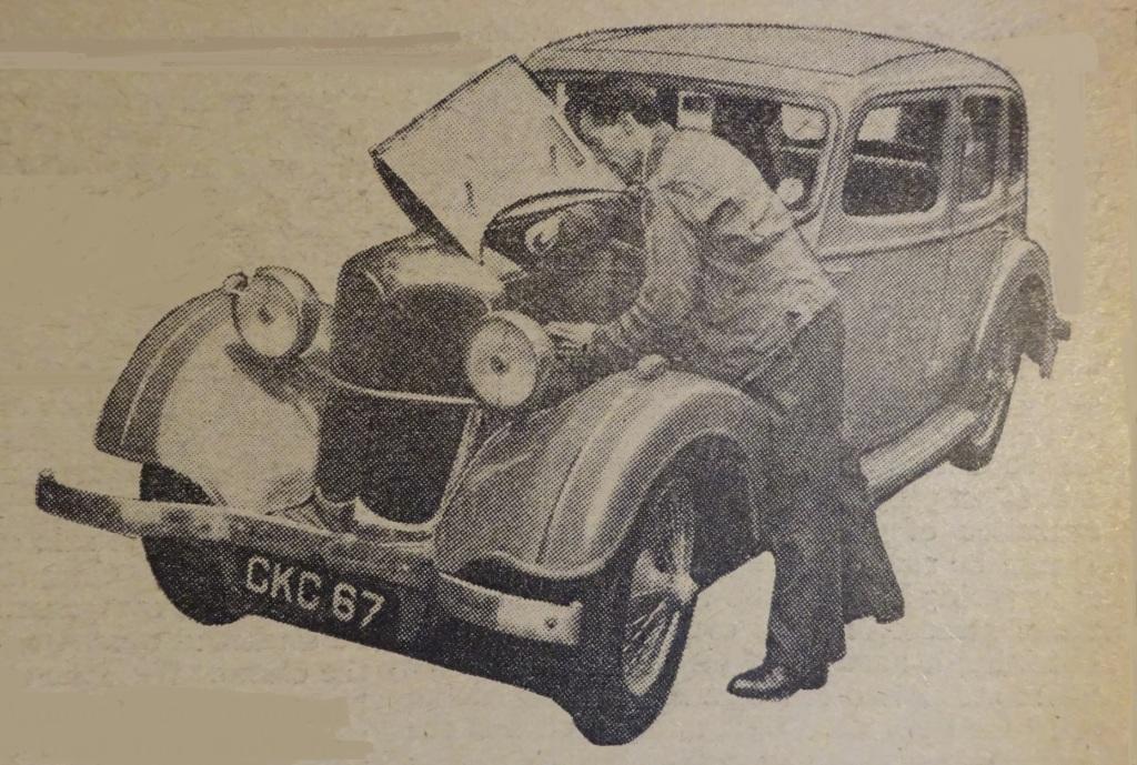
The car shown CKC67 is a Monaco 9, chassis S67Z.
Overhauling the Riley Nine
By A Thomas
PRACTICAL MOTORIST AND MOTOR CYCLIST - OCTOBER, 1955
Part 1
The
Oil Pump: Luvax Shock Absorber: Decarbonising and Valve Grinding: Valve
Spring Removal Tool: Brake Layout: Balancing the Brakes: Adjustment:
Fitting New Pistons.
Lubrication
of all points is of great importance and Riley owners are fortunate in
having a chassis equipped with automatic lubrication which ensures
practically all points being thoroughly lubricated so long as the oil in
the container under the bonnet is kept at the correct level.
A
few points are not covered by the automatic system and these must he
attended to with the oilcan. They are: - front brake, camshaft, hubs
(every 5,000 miles), gear selector joints, brake-rod control joints,
distributor, fan and dynamo. A heavy grease is recommended for the
dynamo, a knurled cap being fitted at this point.
As
regards the engine it is recommended that the oil be changed every
1,000 to 1,500 miles; the drain plug is located on the off side. The
capacity of the sump is approximately seven pints, but it is wise to
take a reading off the dipstick whenever replenishing.
Oil pressure is controlled by a relief valve situated on the same side as the drain plug. The usual pressure at average road speeds is approximately 50 lb per sq.in. The pressure can be raised by slacking off the locking nut and turning the screw inward. Trouble
with the oil pressure rarely occurs, but in its event the plunger and
spring should he removed and the former examined and filed if pit marks
are found on it, as these will affect the seating. In extreme cases it is sometimes necessary to recut the seating with a cutter.
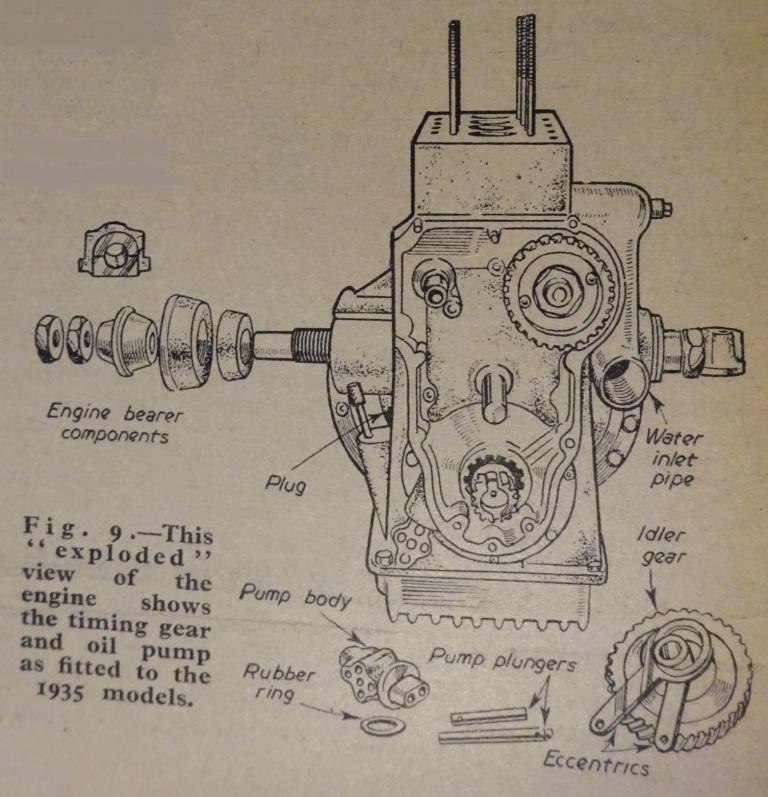
The Oil Pump
On
the later "Nine" model, the 1936 series, a new type of oil pump was
fitted, consisting of an oscillating body, having four ports which
register with inlet and outlet holes in the timing cover, and driven
from the intermediate timing wheel by means of an eccentric and link
connected to a plunger, which passes through the centre of the
oscillating body. The plunger on
the downward stroke pumps the oil through the bottom delivery port and
at the same time draws in a fresh supply from the upper suction port. When
it rises on the upward stroke the oil is forced out through the upper
delivery port and a fresh supply is sucked in from the bottom suction
port. In effect the pump is double acting and delivers oil at a constant pressure to the oil filter on the left of the timing ease. Fig. I shows the pump and timing cover.
The
relief valve on this type has no adjustment, but if it is desired to
raise the oil pressure longer plunger springs can be obtained. The
ribbed container shown in Fig.1 encloses a filter and this should be
removed every 2,000 miles and cleaned, petrol being the usual medium.
Drainage
and replenishment of the gearbox oil are accomplished by removing the
gearbox cover inside the car. There is rather a multiplicity of screws
securing the cover, so that a ratchet screwdriver will be a sound
investment. The gearbox filler plug is on the top of the box and is
immediately noticeable.
The level plug at the rear of the box is not, however, easily noticeable. Always remove this plug when replenishing to ensure that the box is not overfilled. The capacity of the gearbox is approximately 4 1/2 pints.
Re
the rear axle, the filler and drain plugs are in the conventional
places and access is obtained via the luggage container; the floorboard
is either hinged or detachable.
On
the 1935 series the propeller shaft was enclosed in a torque tube, the
front universal joint being included in the automatic chassis
lubrication system. The rear muff coupling (as it is called) receives its supply of oil from the differential housing.
On the later 1936 series the ‘‘Nine‘‘ was, for the first time, fitted with an open propeller shaft. The
universal joint at the front end this shaft consists of a vibrationless
rubber coupling which calls for no attention other than a check over
the nuts and bolts for tightness.
It
should be noted that the bolts on the coupling are made of specially
tough hi-grade material and will stand more than normal tightening and
the use of an extended-length lever is permitted if it is necessary to
exert extreme pressure on the nuts in order to bring the split pin hole
in line with the slot. If the
nuts are not correctly tightened the sleeves enclosed behind them will
rock, and destroy the flat abutments, and no amount of subsequent
tightening will rectify this. On
certain models fitted with this open propeller shaft the rear joint
consisted of a sliding yoke which requires to be lubricated through the
lubricators provided; they require attention every 5,000 miles.
If
the Illustration of this part is closely examined (Fig. 2) It will also
be seen that arrows are stamped on both the propeller shaft and the
differential tail shaft which projects from the differential housing. In
the event of the removal of the propeller shaft it must be replaced
with the arrows in line with one another, otherwise the shaft will be
out of balance.
Careful
lubrication of the hub bearings is essential, as over lubrication will
cause the oil to work through on to the brake shoes. Engine oil is
normally recommended for the hubs, and this can be injected by means of
the oilcan. A good plan is to mix the oil with a thicker gear oil and so reduce the possibility of oil escaping on to the brake shoes.

Adjustments
There are a number of adjustments of a simple nature which the owner can very well make himself.
Commencing
with the steering, an adjustment screw is provided on the engine side
of the steering box which locates in the steering box bush and contacts
the end of the segment shaft. When
end-float becomes apparent in the shaft the locking nut on the
adjustment screw should be slackened off and the screw turned inward
until the float is eliminated. It
is advisable to jack up the car when doing this and turn the steering
wheel occasionally to ensure that the screw is not overtight, as this
will make the steering unduly stiff.
Steering Play
At the top of the steering column an adjusting nut and locknut are provided immediately below the steering wheel. If
there appears to be an excessive amount of up-and-down movement these
nuts should he tightened up by means of a " C " spanner.
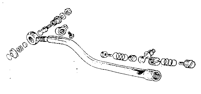
Play in the steering box is often confused with slackness of the tiller-rod joints. To tighten these remove the split pin and screw in the end plug. On
the 1936 series the track rod is fitted at one end with a knuckle joint
which is not detachable, and at the opposite end the knuckle joint,
although detachable from the rod, cannot be further dismantled. Fig
3 shows the parts in the order of assembly as fitted to the tiller rod,
and it should be noted that the parts depicted are identical with those
fitted in the track rod, with the exception of a slightly modified ball
joint.
Fig 3.The tiller rod, dismantled to show the component parts.
Luvax Shock Absorber
Luvax double-action shock absorbers are fitted to both the 1935 and 1936 models, and these will call for attention at intervals. The
most important point is to see that they are kept well filled with oil
use only Luvax shock-absorber oil, as engine oil or gear oil is useless.
The removal of the filler cap will reveal a square-headed screw, which is the adjustment screw. Rotation
of the screw downward will increase the damping effect, and rotation in
the reverse direction will decrease the damping action. When
adjusting the shock absorbers, never rotate the screw more than a
quarter-turn at a time, because the smallest adjustment makes an
appreciable difference.
The
springs are not gaitered, so that in the event of the springing
becoming harsh it is a simple matter to spray them with penetrating oil.
Decarbonising and Valve Grinding
If
decarbonising is carried out during cold weather, first run the engine
for a short time to warm up the parts as it is more comfortable to work
with the metal parts warm. The 9 h.p. Riley engine is particularly
simple to decarbonise, as it is possible to remove and dismantle the
cylinder head without disturbing either the valve or ignition timing.
First drain the water from the engine, and meanwhile remove the bonnet, ignition leads, sparking plugs and rocker boxes. The rocker boxes are detached by undoing the three dome-shaped nuts which hold them in position. As the boxes are sometimes tight it may be necessary to insert a screwdriver to raise them. After this, it should he possible to pull them off without difficulty. Be
careful when applying a screwdriver not to bruise the face of the box,
or trouble will he experienced in obtaining a satisfactory oil seal when
reassembling.
With
the rocker boxes removed the cylinder head holding-down nuts will be
exposed. After removing the holding-down nuts the connection pipe
between the cylinder head and rubber hose should not he disturbed. It
is preferable to push the rubber hose upward toward the radiator after
slipping off the clip, since the replacement of the connection pipe, if
it is removed, is sometimes a difficult matter.
Valve Spring Removal Tool
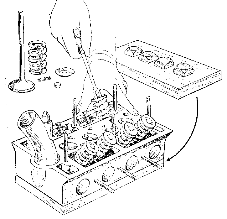
With
the cylinder head removed it in an easy matter to remove the valves,
cotters, cups and springs, provided that a simple tool is made. Obtain
a block of wood 4 in. wide, 13 in. long and screw on to it four pieces
of wood ¾ in. thick, 2 in. long and 1 1/4 in. wide place the cylinder
head on the wooden block so that the combustion chambers register with
the four pieces of wood which have been screwed on to the larger piece.
Compression
of the valve springs with a screwdriver will then be simplified as each
valve will rest against the wood, so that the spring and cotter can be
inserted or detached without difficulty. Fig. 4 shows a wooden block and
valve compressor tool. The tool illustrated for compressing the valve
springs is also very useful, but a similar effect can be obtained by
using a good-sized screwdriver.
Fig. 4.Method of extracting valve Spring cotters.
Valve Grinding
It
is not proposed here to describe the actual operation of grinding in
the valves, but it should be remembered that the insertion of a light
spring between the valve and its seating when grinding in will
considerably assist in obtaining a good gas-tight joint. The valve heads
are slotted so that a screwdriver can be used for the rotary action
employed and the valves are also numbered to ensure correct replacement.
When
removing the carbon deposit on the pistons turn the engine until only
two pistons are up to the top of the cylinder and pack the remaining two
with rag to prevent carbon from working into the bores. Sharp tools
should not be used for scraping pistons, as there is a danger of making
deep scratches in the soft aluminium, to which carbon will readily
adhere in future. Do not scrape off the deposit on the piston crowns
right up to the edge, but leave a band of 1/8 in. to 1/4 in. wide to act
as an oil seal. On no account should emery cloth be used to give a
final polish to the pistons, for in all probability some of the finely
powdered emery will find its way down between the piston skirt and
cylinder walls and cause subsequent unnecessary wear. The surrounding
face of the cylinders should be cleaned of carbon and attention can then
be turned to the cylinder head.
The
exhaust and inlet ports, as well as the combustion chambers should be
scraped absolutely clean of carbon. The valves should be similarly
treated, and then all parts of the head thoroughly cleaned.
Reassembly
It
is important when refitting the valves to smear the stem with a little
engine oil. The packing on the induction manifold should also be smeared
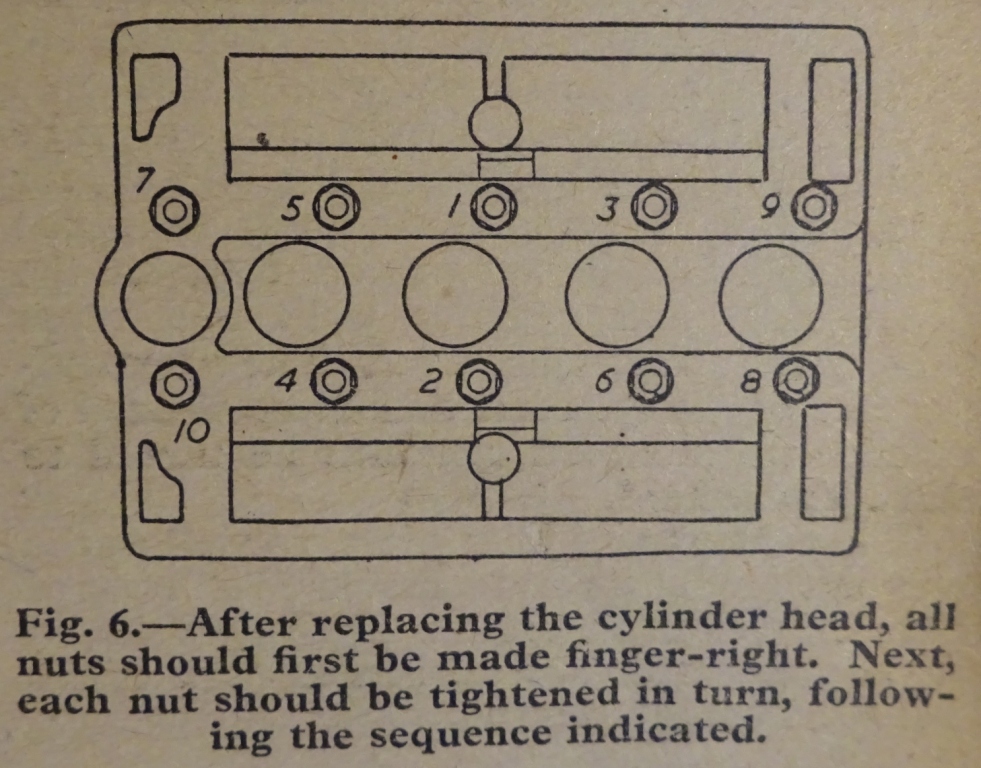
with some jointing compound to ensure a good joint. Before replacing
the cylinder head smear both sides of the gasket with jointing compound
and see that the faces of the cylinder head and block are quite clean.
The head can then be replaced and tightening down of the nuts proceeded
with as shown in Fig. 6.
With
the head well tightened down, replacement of the carburettor,
connecting up controls, etc., can be proceeded with in the reverse
manner to dismantling.
The
tappets will require readjustment as the result of grinding in the
valves, and they should be roughly set in order to run the engine for
warming up before finally setting to clearances of .002in. inlet and
.003in. exhaust, with the engine hot.
Brake Layout
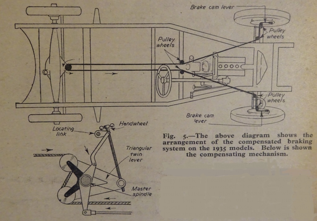
Fig.
5 gives a diagrammatic view of the braking system. A single cable is
used, and as the two ends are secured with brake cams on each front
wheel it is clear that the cable must pass the length of the car in a
loop. Commencing at the nearside front wheel, trace the path of the
cable to a pulley wheel situated below the universal joint. From there
it passes round the bottom pulley of the compensating mechanism to the
top pulley and from there to a further pulley situated on the rear axle
housing. From the pulley on the axle housing, the cable returns to the
offside front wheel brake camshaft, via the compensating mechanism as
before, but in the reverse direction.
Depression
of the brake pedal causes the compensating mechanism to swivel on the
master spindle in a clockwise direction. Consequently the lower section
of the brake cable controlling the front brakes is pulled toward the
rear of the car and the upper section of the brake cable controlling the
rear brakes is pulled toward the front of the car. Thus all four brakes
are operated together.
Balancing
When
balancing the brakes all four wheels should be raised clear of the
ground by means of the jack, and suitable chocks should be inserted
under each axle. It is important in the case of the rear axle that the
blocks be placed under the axle case and not under the jacking plates.
Once the car is jacked up the clamp on the compensating mechanism should
be slackened off. A split pin and nut secure the clamp. With the clamp
slackened off the brake pedal should be applied sharply several times to
centralise the brake cable.
Retighten
the clamp with the brakes fully applied by wedging a piece of wood
between the brake pedal and the seat. With the wedge still in position
check the balance of the brakes by hand. If approximately equal
resistance is felt when the wheels are rotated the brakes may be
considered to be in balance. If
difficulty is experienced in obtaining balance of the rear brakes,
adjustment is provided in the form of a setscrew and lock nut on the
nearside rear brake camshaft. If the brake shoes on the offside rear
wheels are applied before those on the nearside equal application can be
obtained on the nearside shoes by turning in the setscrew. If the
circumstances are reversed the setscrew should be turned farther out.
Adjustment of Brakes
The
following notes refer to the cable- operated brakes as fitted on the
1935 series 9 h.p. models. On the later 1936 series Girling brakes were
fitted and instructions with regard to maintenance of this type differ
in many respects.
If
it is suspected that oil is present on the brake linings remove the
brake drums and examine the shoes. In the event of oil being found the
shoes should be removed and thoroughly washed in petrol until the oil
has disappeared. Before replacing the shoes rough the linings with a
file or rasp.
In
detaching the brake-shoe springs the safest method for the
inexperienced owner is to tie a strong piece of cord round the hook of
the spring at the top, and pull the cord until the spring is extended
sufficiently to slip it off the shoe. It is always advisable to mark the
position of the shoes before taking them off and so ensure that they
are replaced correctly. Difficulty is frequently experienced in
balancing the brakes when the shoes have been removed and then replaced
in a wrong position. To remove the brake drum the car should first be
jacked up and the road wheels removed. Removal of the road wheels will
reveal two screws with flat heads which hold the drum in position.
Remove these screws and then insert a screwdriver between the brake drum
and the dust cover. In most
cases a little prising will be sufficient to force the drum off the
shoe, but if difficulty is experienced tap the centre of the brake drum
sharply with a hammer, after having secured the screwdrivers in such a
position that an outward force is being applied to the brake drum. When
the rear brake drums are to be removed do not forget to release the hand
brake.
Sticking Brakes
If
the brakes have a tendency to remain on after the pedal has been
returned to the off position jack up the car and rotate each wheel to
ascertain which one is at fault. In the case of a front brake being at
fault it is as well to remove the brake drum and operate the cam lever
by hand and note if it returns to the off” position. If it tends to
stick and has to be pulled back by hand remove the brake-shoe return
spring, thoroughly clean the cam lever and lubricate with a light
machine oil. Weak return springs
may also be the cause and in some cases it is possible to overcome such
troubles by shortening the springs. To do this the spring should be
clamped in a vice and the hook end straightened out. A portion can then
be cut off and the hook reformed.
Fitting New Pistons
If
it is desired to overhaul the engine thoroughly it is always advisable
to remove it from the frame. For this block and tackle is required, but
if this is not available new pistons, timing gears and new connecting
rods can be fitted without removing the unit.
The
cylinder head must first be removed, the engine oil drained from the
sump and the sump detached. To facilitate working below the car it is a
good plan to raise the car on the jack high enough to permit strong
wooden blocks to be placed underneath the frame immediately to the rear
of the front springs. This will enable the jack to be removed from under
the axle and leave sufficient space below the car to work in reasonable
freedom and comfort. In most cases the removal of the radiator will
greatly facilitate the work and is, of course, essential if new timing
gears are to be fitted.
With
the sump removed, the main bearing feed pipes, can be detached and the
split pins withdrawn from the connecting rod bolts. The connecting rod
caps should be cleaned and the number, which will be seen stamped on the
side, noted to ensure correct replacement. If the engine has not been
dismantled since leaving the works the number will be found to be
stamped on the exhaust side.
When
the caps are removed it is possible to push Nos. 1 and 2 connecting
rods upward until the pistons protrude through the cylinder block, with
the pistons exposed above the cylinder block; the circlips retaining the
gudgeon pins should be removed.
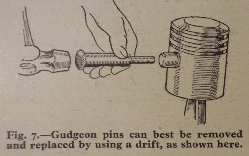
Removing the Gudgeon Pins
Fig.
7 shows the drift which is used to remove the gudgeon pins. This should
be ground down sufficiently to give clearance to the circlips, but at
the same time should retain sufficient thickness to form a shoulder for
locating the gudgeon pins when reassembling.
Pistons
3 and 4 are drawn through the base of the engine; when doing this it
will be necessary to work from below the engine. When the crankshaft is
rotated guide the connecting rod round the journal so that the rod and
piston can be withdrawn complete without damage. The reason why the
front two pistons cannot be withdrawn by the same method is that the
engine bearer bar intercepts the cylinders.
It
is advisable when removing pistons 1 and 2 to have somebody below the
engine to hold the rods when they are disconnected from the pistons,
otherwise they will drop down and damage the crankshaft journals.
Overhauling the Riley Nine
By A Thomas
PRACTICAL MOTORIST AND MOTOR CYCLIST - NOVEMBER, 1955
Part 2
Piston
Clearance: Fitting Gudgeon Pins: Con-rod Replacement: Fitting New
Timing Gears: Brakes: Clutch: Rear Axle: Fitting New Crown Wheel and
Pinion.
Piston Clearance
The
usual piston clearance is .002in. When testing for clearance invert the
piston into the cylinder and insert a feeler of the required thickness
between the piston and the cylinder wall. The gudgeon pins should be
fitted to the pistons first as it is sometimes necessary to locate a
stick on the gudgeon pin and work the piston in the cylinder with an up
and down movement to obtain the required clearance.
When
fitting piston rings the gap should not exceed .008in. and the best
method is to file the ring with a ward file. On all Riley “Nine” engines
there are three compression rings and one stepped scraper ring. The scraper ring should be fitted with the stepped portion downward. To
fit the rings, insert them into the cylinder bore, check the clearance
with a feeler and file the gap as necessary. The fitting of new gudgeon
pins in new pistons is comparatively simple, an expanding reamer should
be used to reamer the pistons to the correct size. The
inside face of the piston boss is usually cleaned up with a suitable
cutter to give clearance for the small-end bush and to enable the rod to
be centralised on the gudgeon when assembling.
Fitting Gudgeon Pins
When
reassembling Nos. 3 and 4 pistons should be fitted to their respective
connecting rods and inserted into the cylinders from below the engine. With
Nos. 1 and 2 connecting rods hold the rod from underneath in such a
manner that the small end protrudes through the cylinder block in this
position the pistons can be fitted from above.
When
fitting the piston to the rod enter the gudgeon pin into the piston as
far as the inside boss and fit a circlip on the other side. Place
the piston over the connecting rod and then insert the gudgeon pin
drift on the same side as the circlip, and feel the connecting rod and
the inside end of the gudgeon pin. When they are satisfactorily lined up the gudgeon pin should he tapped until it locates against the circlip. Fit the circlip in the other end of the gudgeon pin and then the compression rings and scraper rings.
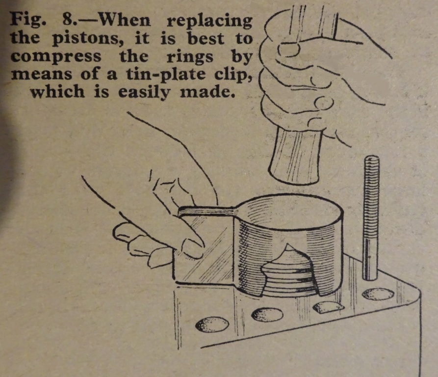
Con.-rod Replacement
When
the pistons are fitted smear oil over the pistons and cylinder walls
and lower the connecting rod into the cylinder until the bottom ring of
the piston rests on the lip of the cylinder, and space out the rings
with the gaps equidistant from one another. Close the ring gaps with a
compressing clip, when the piston can be lightly tapped into the
cylinder with the shaft of the hammer. Fig. 8 shows the type of
compressing clip employed. When the piston is in position in the
cylinder the connecting rod should be guided on to the crankshaft
journal and the bearing caps replaced, making sure that they are
replaced in accordance with the numbers on them.
Before
refitting a connecting rod it is advisable that the alignment of the
rod be checked with the aid of one of the many universal jigs which are
available for this purpose. It extremely important that this alignment
check be made in both planes.
Fitting New Timing Gears
To
fit new timing gear it is necessary first to drain the water from the
radiator, remove the bonnet and front cowl, disconnect radiator hoses,
remove the radiator by undoing the tie rods and nuts, which will be
found under the front cross member, remove the dynamo (three nuts secure
this in position) and disconnect the dynamo wires. Remove the distributor by undoing the clamping nut and lifting off the cover. In
regard to instructions on the removal of the oil pump it should be
remembered that the pump on the 1935 series is not the same as on the
later 1936 series.
With
the double-plunger pump as fitted on the 1935 series, Fig. 9, the two
bolts which pass through the oil pump body should be detached and the
body drawn downward. This will leave the plungers hanging loosely so that it will be possible to detach the rear pump plunger. The front plunger should be detached after the timing case has been pulled slightly forward.
On the later 1936 series the oil pump is dismantled after the front cover has been removed. To remove the intermediate wheel the pin which locks the collar fitted in front of the gear has to be tapped out. The collar can then he removed by prising with a screwdriver, and the intermediate gear removed in the same manner.
To remove the camshaft gears it is necessary to use an extractor since the gears are keyed to the shaft. Before removing the gears straighten out the tab washers and detach the locking nuts.
If
the camshafts are withdrawn completely with the engine in position some
means must be found for locking the tappet or they will drop into the
sump. It is not recommended that the camshafts should he extracted
unless the engine is removed from the frame. Considerable care must be
exercised in prising out the intermediate gear so as not to damage the
aluminium casing when the screwdrivers are inserted behind the gears. Fitting the new gears is comparatively simple, but it is advisable to test each gear in turn before finally assembling. If
one or other of the camshaft gears appears to be tight this may be due
to malalignment of the intermediate spindle. It can be corrected by
cranking the spindle slightly. When
replacing the gears note that the camshafts are marked respectively
I.I. and E.E., these markings indicating the position at which
corresponding marks on the intermediate gear must engage. In
the case of the crankshaft pinion an "O" will be found stamped on it
which should correspond with the "O" on the intermediate gear.
Ignition Timing
To
retime the distributor the engine should first be turned until No.1
piston is at T.D.C. on firing stroke. The distributor should be placed
in position with the lever in the fully retarded position, the contact
breaker point just about to open. The final adjustment of the
distributor can be made by manipulation of the distributor body when in
position.
Girling Brakes
On
the 1936 series model fitted with Girling brakes adjustment of the
brakes is extremely simple. Both hand and foot brakes are adjusted by a
single operation, and when wear reaches a point at which pedal travel
becomes excessive the shoes have to be adjusted closer to the drums.
This is done by rotating the adjuster situated on the inner face of each
brake drum backplate in a clockwise direction. The adjuster should be
screwed up as far as possible; the shoe making contact with the drum
will prevent further movement. When adjusting a “click“ will be heard
and felt at every quarter-turn. When no further movement is possible
turn the adjuster back to the nearest position which gives freedom of
the brake drum. Adjustments should be carried out on each wheel to bring
all shoes into balance.
If
binding of the drums is noticed after this adjustment a sharp
application of the brake pedal will centralise the shoes and correct
this tendency.
The Gear Change
A
very simple adjustment and one which is peculiar to Riley cars is to
ensure that the movement on the steering column coincides with that of
the lever on the gearbox quadrant. If the car is examined it will be
seen that the selector levers are coupled by adjustable control rods,
and in the event of a control rod being out of adjustment the
preselection of, say, first gear at the steering column may not have the
desired effect at the gearbox quadrant.
To
test for correct adjustment push the selector lever to top gear and
then examine the position of the quadrant lever on the box. If top gear
has not been selected uncouple the control rod at the box and push the
lever by hand into top gear. Adjustment of the rod can then be carried
out with the control levers in their respective positions. If difficulty
is experienced in selection of any of the intermediate gears the same
method should be adopted.
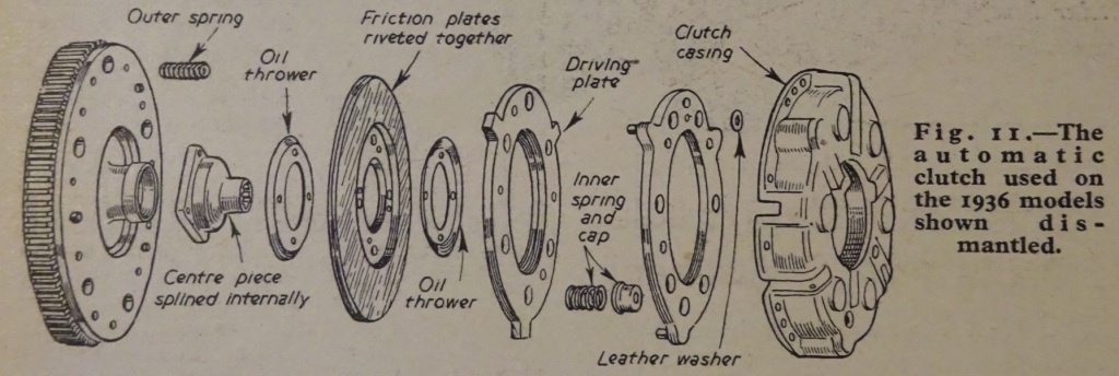
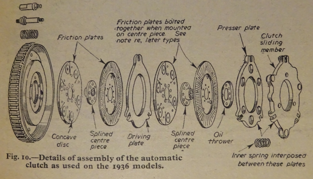
The Clutch
The
clutch is made up primarily of the governor weights and levers, the
presser plate, the friction plate or plates and the sliding plate. Other subsidiary parts will be described later. The general arrangement of both types can be seen in Figs.10 and 11, where all parts are shown in their relative positions.
The
governors must always be free to move in scissors fashion and if
tightness is suspected examination of the pins which pass through the
governor will reveal whether binding is taking place. If necessary
smooth the pins with fine emery cloth. The driving pins should also be
examined, and if grooves have formed as a result of the continual
pressure the pins should be renewed. If the groove formation is only
slight it might be possible to eliminate it by filing.
The
clutch will require little or no attention if it is in good condition,
but it is a good plan if the engagement tends to become fierce to remove
the clutch inspection cover and pour a few drops of paraffin between
the levers, at the same time working the levers with a large
screwdriver. On the 1936 type the tendency of the levers to be tight is
not always due to the lack of lubrication, but is often caused by the
levers binding- on the clutch casing. To rectify this remove the starter
in order to gain access to the lever. A sharp blow with a drift and
hammer will free them a little paraffin can then be poured on.
Rear Axle
The
differential assembly on the 1935 model differs from the 1936 type
inasmuch as the propeller shaft on the earlier model was enclosed in a
torque tube, which caused the differential unit to be mounted at the end
of the tube and then bolted into the rear-axle casing. On the later
(1936) type, with an open propeller shaft, it is possible to detach the
differential assembly from the axle casing without completely removing
the axle (see Fig. 12).
Reverting
to the 1935 type, two adjustments are provided for the crown wheel and
pinion. On the top of the torque tube, directly above the differential
casing, a plate will be seen secured in position by two nuts. This plate
is known as the tail-shaft sleeve lock and, as the name implies, it
acts as a lock for the tail shaft or pinion. If the plate is removed a
tommy bar can be inserted to locate with the serrations of the pinion
sleeve and if the sleeve is moved in a forward direction the pinion will
be forced into deeper mesh with the crown wheel. This adjustment can be
carried out without removing the axle from the chassis by simply
lowering the luggage lid and removing the floorboard. It is not
recommended by the manufacturers that the pinion be moved more than two
serrations either forward or backward, as this amount should be
sufficient to correct any axle noise that is being caused by wrong
adjustment.
At
the side of the crown wheel two adjusters are provided for lateral
adjustment of the bearings. These rarely have to be touched, except when
a new pinion and crown wheel is fitted; they should be adjusted in
accordance with the instructions for the later 1936 series.
As
this type is fitted with an open propeller shaft it is possible to
detach the differential unit by simply moving the road wheels, brake
drums, etc., withdrawing axle shafts and uncoupling the propeller shaft
at the rear. Move the shaft to one side, remove the nuts on the axle
casing and withdraw the differential unit complete with crown-wheel
pinion.

Fitting New Crown Wheel And Pinion
Assuming that new crown wheel and pinion are to be fitted, the following is the method of adjustment
Clamp
the differential housing in vice with dipstick aperture uppermost.
Place the crown wheel in the differential housing and fit
differential-housing cap. It should be possible to push the cap home
until the faces on the cap are flush with those of the housing. If this
is not so, and one side of the cap stands clear of the housing, it
indicates that the adjuster in this particular side is not positioned
correctly. On no account attempt to draw the cap into position by
tightening the nuts, for distortion of the case would take place and
remove any possibility of correct adjustment. With the cap correctly positioned tighten the nuts on the cap until they are slightly more than finger tight.
Observe
the position of the crown wheel in relation to the recess on the
housing flange. The wheel should be lined up by means of the side
adjusters with the centre of the recess to obtain an approximate
position. Adjustment can next be
made by means of the bearing adjusters at the side of the housing until
only a fractional amount of side movement can be felt in the crown
wheel. On the side of the crown
wheel a centre dot will be found, which must always be married up with
the centre dot on the pinion. To simplify meshing the gears in the
correct position chalk mark the corresponding position on wheel and
pinion.
Insert
the pinion and housing with the oil holes in the pinion housing in line
with the corresponding hole in differential housing. The locking screw
for the pinion lock ring will always be on the right hand side, this
indicating the correct position. Be sure that the teeth mesh correctly.
With pinion in position, rotate the crown wheel and test for drag in gears.
If
drag is felt in the gears it will be necessary to adjust as follows :-
ease pinion rearward and insert shim or shims of the required thickness.
Adjust alignment of crown wheel by means of bearing adjusters.
Compensate both adjustments until gears are free from drag.
End
|